In this post I have tried to capture pictures of the radiator support system as well as good shots of the Stainless Steel lines to and from the engine-radiator. Here goes:
In the photo above, you can see a bit of how the radiator support was constructed. Angle iron constituted the main structure from frame rail to frame rail for the the front and the back of the system. Small holes were drilled in for increased airflow. At the end of the angle iron, you can see another small piece of angle iron welded on with a drilled bolt hole to attach the system to the frame of the VW. The entire system is secured with four grade 8 bolts and nyloc nuts.
Front to back on the left and right of the system is yet another run of angle iron. This is welded to the angle iron that runs from frame rail to frame rail. Three holes were drilled per side to mount the radiator then to the front to rear angle iron as seen below. Notice in the picture above, a rubber pad separates the radiator from direct contact with the angle iron to help dampen some of the vibrations and torque of the unibody of the bus.

Once the side to side and front to rear angle iron was measured, cut, and welded into a square structure, the next step was to take some sheet metal and cut to size to fit the square structure. It was welded on to the bottom of the structure and 2.5" holes were drilled into the sheet metal (5 holes left to right and 5 holes front to back) to allow air to flow from the top of the system down through the radiator (or to be pushed by the 2 14" pusher fans) and out. Fine grade wire mesh from a farm and ranch store was then liquid nailed inside the sheet metal to prevent gravel and rocks and twigs, etc. from make contact and possibly damaging the radiator itself. This system allows the whole radiator system to be dropped as one unit by removing four bolts (and of course draining coolant and disconnecting the two hoses).
Also notice there is no air scoop or boxing of the radiator cavity along the side rails or back space. It simply sits there as is.
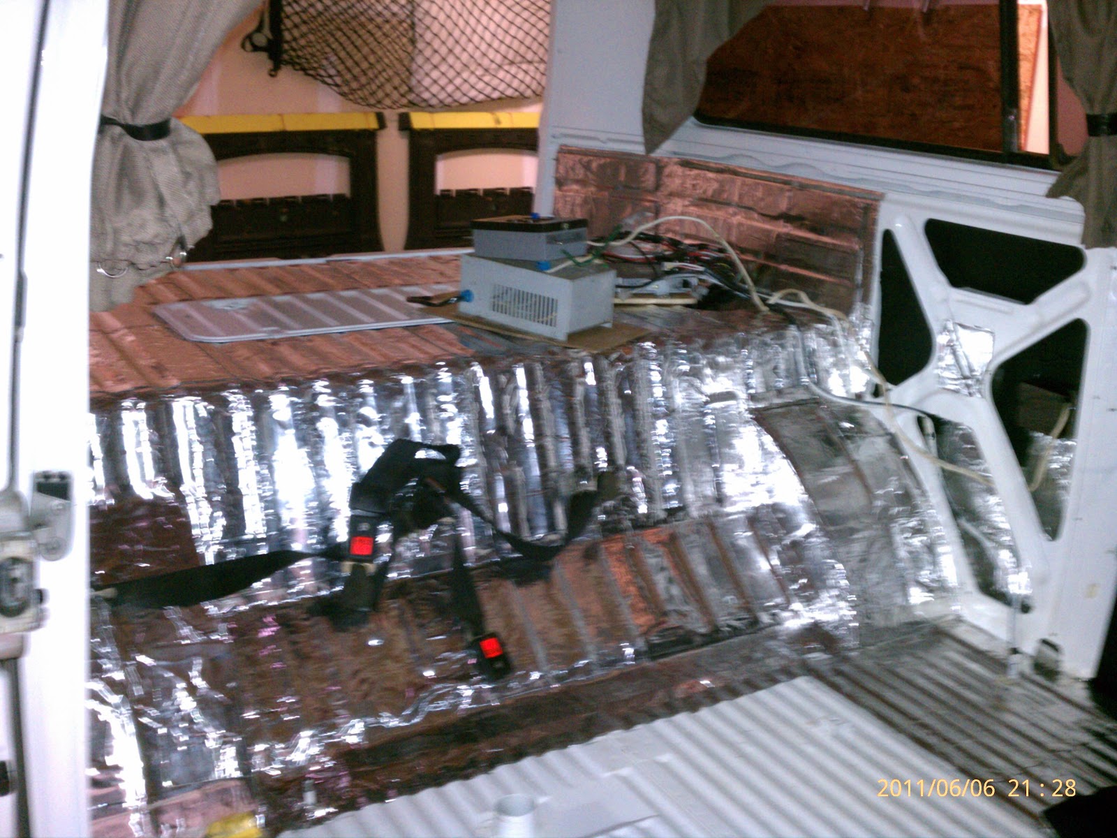
The next picture attempts to show the space between the top of the low profile fan and the floor of the bus; still a decent amount of space. I'll also point out that the rear of the radiator system sits higher in the belly of the floor pan and drops approximately .5" in the front. This allows coolant to drain from the front facing petcock in a controlled and easy manner. Point is the space between the top of the fans and the floor of the bus is greater in the front; and this picture is taken from the rear most vantage point...
The following pictures are shots of the custom stainless steel lines and support mounts that span the distance between the engine and the radiator. Sorry, they aren't in any order and you'll have to do some detective work to determine driver side and passenger side. I'll let the picture do the talking:
The picture below is how I control the fans. I did not build the fan system into the Subaru ECU, which controls fans based on both temp and speed. My fans are simply controlled by a thermo switch (210*) placed in a coupler T immediately after the coolant manifold exit. So far based on watching my Scan Gauge, which reports coolant temps via the temp sensor as reported through the ECU, the fans seem to kick on at 206* and run until about 196*.
The following pictures are how I plumped the thermostat. You'll notice Tom Shiel's adaptor, which will allow me to set up a heating system without affecting the thermostat by reading luke warm coolant.
You can see the radiator return line at the bottom. The hose attached to Tom's adaptor is from the pressure tank, which is feed coolant from one of the stainless pipe runs immediately following the coolant manifold exit and fan thermoswitch. That way, hot coolant is run from the manifold, through the thermoswitch and the takes two paths: one to the radiator and one to the pressure tank, where it is then routed down to the thermostat adaptor.
The top hose you see is the original Subaru heater return line. Currently, I have the rear of the coolant manifold (i.e. the heater supply) simply connected via a short hose to the return pipe (just a big u-bend). Once I am ready to set up my heater cores, I will run the entire system from the original heater supply and heater return pipes as a separate and complete system; no negative effect to the coolant temperature controlling the thermostat!
One word of caution regarding the Tom Shiel's adaptor: I actually had to shave down the adapter in the area where is is closest to the oil dip stick tube. The adapted made contact with the oil dip stick tube and I was not able to get a solid seal around the thermostat housing. A Drimmel tool and 10 minutes and I was in business, but not before I put a gallon of coolant in only to realize the problem as the gallon of coolant spread across my garage floor. Just something to be aware of (don't know if this is a common problem or a "my" problem).


