Tuesday, December 28, 2010

ECU Plugs -- Wiring Details

I have been working further on the wiring for my conversion.  At first when I saw the mess of harnesses that I pulled from the donor Subaru vehicle, I thought I would farm out the wiring work.  Well, it turns out no one wanted to do it and/or no one was prepared to work on a 2001 OBDII wiring system when I started!  Guess I'll save some money on this one.

As detailed in an earlier post, I worked through the harness and identified each connector one by one and taped and wrote the plug number and system info.  I then started to windle the wiring down one wire at a time.


And ended up with a big mess of unuseful wires!


I then started detailing the wires from each of the three plugs going from the ECU out to the subsystems and captured all of the pertinent info in docs (connector number (male and female), wire color, and terminal numbers from/to each connector and subsytem each wire belongs to).  Please be advised that this information my be incorrect (tired, blurry eyes) and use it at your discretion.  Also please note that the wiring schematics are for a 2001 USA Subaru Impreza with a 2.2l N/A engine and an automatic transmission.  I am also retaining the radiator system and the A/C system and running fans and components for eac directly from the ECU.


A/C Cooler and rear heater

 First up is the rear heater.  I snagged a rear heater assembly from a salvaged Vanagon in my local salvage yard.  It was pretty dirty and I am not entirely sure that the core is good.  There was evidence that perhaps some leaking had occurred simply based on the junky gook that coated the outside of the core when I picked it up.  I suppose I could run water through it to see if it hoold, I just haven't yet.


The idea will be to place it in the rear of the bus under the Z-bed.  It will take up some space, but I'd rather have heat then an extra cubic foot of space. 


The potential negative of placing the heater assembly under the Z-Bed is that the lower access door will need to be removed and replaced by a vent of some sort, or the door itself will need to be modified.


I will also need to creat some kind of mounting system.  I am thinking about removing the orginal vent tube to route my heater lines through so I don't have to cut or drill holes in the floor.


The next step is to figure out placement of the A/C cooler.  I am considering two options: one is to mount the A/C cooler under the radiator so the airflow and dual electric fans can be used on both the A/C cooler and the radiator.  I don't know exactly how much protrusion this will create under the bus.  Once I start mocking up the air duct system for the radiator, I will take some measurements and make a decision. 

Option #2 is to mount the Subaru A/C cooler on the outside of the framerail between the rocker panel (where the propane tank usually sits).


The only problem with this approach is that it will require additional fans, relays, and wiring to the underside.  And since I don't have the additional fans, I am not sure how far down the whole system would sit below the rocker panel...  Mounting the A/C cooler under the radiator would prevent the need for that extra work.

Thursday, December 23, 2010

Engine installation

With the engine and transmission mated together, it was time to roll the unit under the bus and get it bolted in!  The process actually went very smoothly.  I had to take the throttle body off to fit the unit under the bus (I lifted only the rear passenger side of the bus just enough to roll the unit under).  I had the motorcycle jack under the engine and a hydraulic floor jack under the transmission to support both ends.  Once the unit was under the bus, I lowered the rear corner and slowly started to jack up the engine first, then the transmission and continued this way until the everything was up and aligned. 


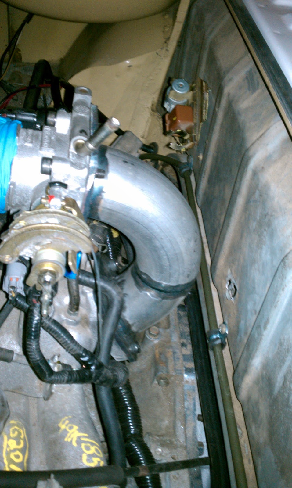
I bolted the rear (front of the bus) of the transmission first and then started working on the two bolts that attach to the upper cross member.  You can see the close fit against the fire wall after I reinstalled the reverse throttle body.  Without the reverse and in stock location, there would just be no way to squeeze an air intake pipe on the throttle body.


I had a slightly harder time getting the bolt holes to align on the upper cross bar.  After poking around, I realized that the heater pipes on the passenger side where interfering and not allowing the engine and transmission to completely lift as high as necessary ( I am not using a reversed coolant manifold; it stayed in stock orientation).  I used a cheater bar and gently, very gently, bent the top most heater pipe down just enough to allow the engine/transmission to achieve full height.  Once I did that, the bolt holes on the upper engine cross member aligned with no problem!  


I had to make one other modification to fit the engine and that was with the original airbox support bar.  In stock form, it interfered with the Subaru oil filler cap and also prevented the engine from fully sitting in the bay.  I had to bend just enough of the end up to allow the oil filler cap to fit properly.  The metal was brittle enough that as I bent it up, it just snapped off, resulting in a shorter section of the original air box support bracket.  Oops.  Non-returnable modification #1.


Everything else went on pretty smoothly.  I reconnected all of the transmission accelerator lines from the pedal assembly to the new Small Car throatytle cable set up.  Everything fit perfectly. 


Because of the reversed throttle body set up, my accelerator cable in stock form is slightly too far forward and ends up sitting almost exactly below the housing.  I think it will work in this arrangement, but I may try to move the cable retaining clip further toward the rear of the bus to give a better arc from the end of the cable housing to the throttle assembly (so the upperward bend isn't so sharp).  I think this will be easily achieved be taking the cable retaining clip and simply flipping it 180 degrees...I may loose my spark plug wire holder clip, but oh well.


Next up is getting the rear cross bar modified to fit.  I am using the Small Car engine mount system and purchased the two inner and two outer rubber mounts.  This set up is intended for a Vanagon install, so either a custom cross bar needs to be created to fit, or a Vanagon cross bar modified to fit.  I choose to go the latter route.


I found a Vangaon rear engine cross bar at my local slavage yard for pretty cheap.  The first thing that had to be done was to cut out the orginal framerail brackets since they were too tall (didn't allow the bolt holes on the bar to align with the rubber mounts) and too wide (the frame rail distance apart is different on a Bay versus a Vanagon.


Once I had the framerail brackets off, I test fitted again and realized the bar is still a bit too tall to fit, meaning the top of the engine cross bar hits the bottom of the frame rail before the bolt holes fully align.  It is off only by a 1/4 inch at most.  I marked up the location and width of the frame rail on each side of the engine cross bar and will have to cut the end off and recess the top of the bar a 1/4 of an inch plus the thickness of a steel plat that will be fabricated to mount to the bottom and wrap up the outside of the framerails.  I haven't gotten to that point yet but hopefully will shortly after the holidays.  I'll try to take some exact measurements and post those for any interested.


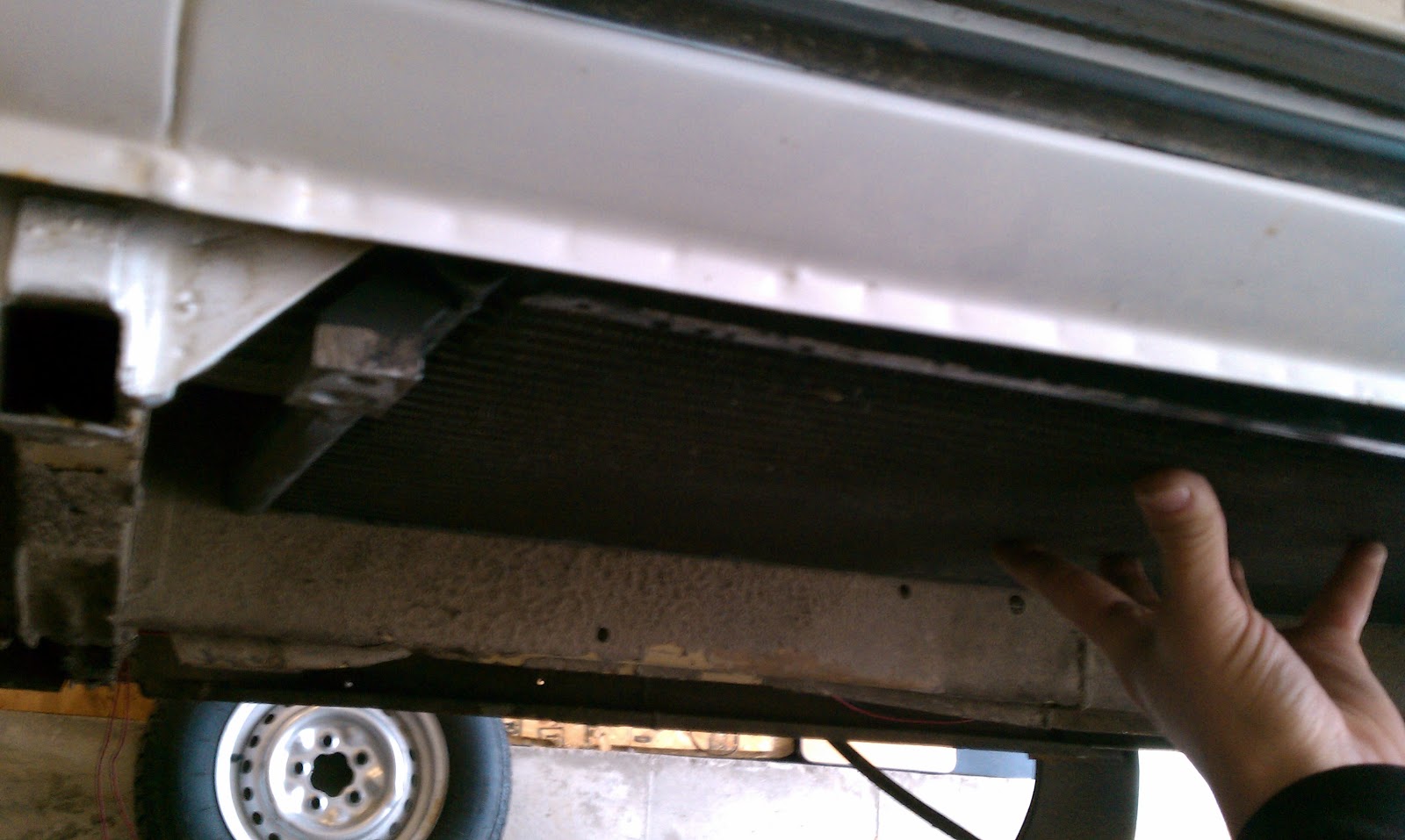
Next up is the radiator placement and duct work, the fitment of a rear (Vanagon) heater asembly, and the A/C cooler and system install.

Friday, November 19, 2010

The mating

The engine and transmission are together finally after what has felt like an eternity.  It is all the small things that add up to time delays. 


I was able to get a little more work done and installed the new KEP hub and flex plate, got the adapter bolted to the engine,
  
and the torque converter in.  


I am now excited to get the combo installed in the bus so I can focus on the wiring and running the cooling set up, heater set up and A/C.  I feel vaguely guilty that the starter is still grimy while the rest of the transmission is looking good. 


I used German Specialties for the transmission reseal and while the finished work looks good, I will not go back.  Enough said.

I still need to have the rear mounting bar built to fit the Small Car mount system and Vanagon rubber mounts.  Once I get the engine and transmission positioned and the transmission bolted in place, I will have BMF take the specs and dimensions to build the bar.  A cinch strap will have to suffice for a short while to support the rear (front) of the engine until the bar is built and ready to install.

Another custom piece will be the radiator shroud/air duct, which I intend to have BMF build as well.  The radiator and fans have arrived so I can start specing that out now.   Getting closer...


Wednesday, November 10, 2010

Catching up

It has been awhile since my last post, but that doesn't mean I haven't been working forward on the conversion.

I have finally buttoned the engine up.

I have installed the Small Car shortened oil pan.

I have the Small Car engine mount installed, Vanagon rubber mounts, and will be building a custom cross bar to fit the Small Car mount system and work with my frame rails.


I came across a post on aussieveedubbers forums from Hellbus who worked with Custom VeeDub, which used to be Custom Offroad (COR), out of Australia to build a throttle body reverser. I decided that I would do the same thing and avoid the troubles of reversing the manifold, reversing the wiring harness, and avoid having to relocate the alternator and A/C compressor. With the reverser, everything stays stock!


I am using BMF Perf. out of Brighton, CO. Chris is the owner and he does fantastic work at reasonable rates. Take a close look at his welds on the throttle body reverser!

Other small tasks I have completed are to install the flexible dip stick tube, finish up the gas tank reinstall, order a custom radiator with dual pusher fans from Wizard Cooling, which hopefully will be here in about a week (pic to come!). I am working with Chris from BMF Performance to create a custom air duct and scoop to fit the radiator between the frame rails.
I have also dropped the transmission and differential for service. I ordered a reseal kit for both the transmission and the differential and drilled out the stud and nut hole on the top driver side of the bell housing to bolt on the adapter plate per KEP and Tom Shiels' instructions.
And finally, I have started in on the wiring harnesses. I have meticulously identified each and every connector on the engine harness, the front wiring harness in the engine bay and the bulkhead wiring harness in the cab. Each of the blue items is a piece of tape the denotes the wire number and function according the the wiring schematics out of the factory manual.
This is a shot of the Front wiring harness with the connectors all identified with blue tape.

Here is the location and function guide. The red lines suggest the components of the wiring harness I will delete and remove from the harness. I cut the harness just before it crosses the front of the car and this may have been a mistake. I may need to extend and re-wire some of the harness to fit my application.


Here is a shot of the bulkhead wiring in the engine bay:

And this is the intended delete list for removal:


Here is the in-compartment bulkhead wiring:

And the delete list:

Friday, October 8, 2010

Timing Belt

Next project up is to change the timing belt on the Subaru engine. I purchased a Gates complete kit with new tensioner and pulleys/gears from the local CarQuest since I just know very little about this engine and access the timing belt is a lot easier on the stand then in the car.
First step is to remove the crank pulley and tensioner. Then on to the plastic timing belt cover. Easy enough
For the most part, this was a pretty straight forward project. I followed a technical forum write up by Meaty on North American Subaru Impreza Owners Club Website as well as the instructions that came with the kit and the pdf service manual, which I downloaded from Ken Gilbert's Website. All three were slightly different in instruction, so I had to make some decisions along the way.


The biggest worry I had was regarding the right side cam gear timing mark. I actually had two different marks, a white paint dot and an engraved dash in the gear face itself with pink paint.
In the end, I went with the physical indented dash with the pink dot. I followed the instructions, lined the belt up appropriately, double checked everything, and then pulled the tensioner key to put the belt under tension.
The time of judgement came after when I rotated the crank two full revolutions to see if all three timing markets still lined up again.
Yes = Did it right
No = Did it wrong
My results YES = Did it right!

Air Intake Manifold and Throttle Body

Here is a top look at the air intake manifold and throttle body (taped up). As it sits in stock position, the manifold has the throttle body facing toward the transmission. Fine in a Subaru, but in a Bus it won't work.

If you notice how close the throttle body extends in relation to the engine mating surface for the transmission, and if you think about the alignment of the VW transmission bellhouse almost inline with the firewall above, you can see that there is going to be a conflict. There is no way to attach an air intake pipe/filter to the throttle body without interfering with the firewall and gas tank.

The most common remedy for this is to flip the throttle body 180* and then flip the wiring harness 180* again so the fuel injectors still fire in the correct order. The problem with this solution is that the throttle body then intrudes into the space that the alternator normally sits, requiring a custom fabricated bracket system to reposition the alternator where the a/c compressor normally sits.

My dilemma is that I am not sure I want to screw around with fabricating a bracket, and there are none to purchase aftermarket right now. Richard at RJES is potentially going to sell an off the shelf alternator bracket to help this problem, but it is not available currently. An added problem is that this solution eliminates the possibility of an A/C compressor since the alternator has to be be repositioned to the spot the A/C compressor us ally sits. I kind of like the idea of retaining the A/C compressor so we can have air conditioning. Windows down with a two year old and a 10 month old is not always a good thing.

However, the alternative to reversing the manifold is to modify the firewall or potentially run without the firewall (may not be a smart choice without a fire repression system installed). AND, I don't know of the air intake pipe will even fit without the firewall due to the gas tank. I have to mock the engine up in place to see what type of, if any at all, clearance I have.

In the meantime, I pulled the intake manifold off.


The coolant heater manifold sit underneath the intake manifold.


A lot of people doing this conversion on Vanagon VW have the coolant manifold reversed to better fit and locate with the original Vanagaon coolant lines, which sit on the top passenger side of the engine compartment. Since I don't have stock radiator or lines to mate up, I don't have to reverse the coolant manifold. However, I am considering doing so since most/all radiator coolant schematics are based on this manifold being reversed. It is an added cost but it would make routing and plumbing against common schematics very easy. Tom Shiels has quite a bit of excellent info on coolant and radiator set ups on his Website although it is all for Vanagon conversions not Bays like mine.
The decision to reverse the manifold or modify the firewall/fuel tank will have to wait until I can roll the engine under the bus and jack it up into rough position. Before I do that, I have to finish the tank restore project and replace the timing belt on the Subaru motor.

Fuel Tank Restore

While I had the engine out, I decided to pull the gas tank. I had noticed that the filler tube on the gas inlet was cracked and potentially the cause for some of the strong gas fume smell inside the bus (we had to roll windows down quite a bit on the drive back from Santa Fe). The only way to replace this piece is to remove it from the inside, which requires pulling the tank out , which requires removing the engine.


Pulling the tank wasn't too hard with the engine out. I followed Richard Atwell's DIY Fuel Tank Restore thread. I was shocked at the amount of rats nest hiding out behind the firewall after pulling it off.


As I looked closer, and while holding my nose, I saw the skull of the culprit!


It turns out it wasn't only the skull; it was the entire skeletal system from skull to tail and toes included! Oh man, did it smell. Pee and poop coated the bottom of the tank bay and I am still spraying it down and scrubbing it out. I can't get the piss smell out of my nose...


The tank itself looked pretty good, dirty, but no noticeable holes.


I wonder what rat hair and pee/shit does in regard to resistance drop? My gas gauge never did work below the half way mark...maybe I know why now (pic of the sending unit).


I ordered a POR-15 Fuel Tank repair kit from Don at the POR-15 outlet on eBay:

POR-15 AUTO FUEL TANK REPAIR KIT GENUINE POR15 (Item Number: 230383638934)


I opted to go the full kit rather then follow Atwell's mueratic acid route.

I am planning to prep the tank and apply the POR-15 this weekend.


I also ordered a new fuel filler neck (PN211 201 119) and a sending unit (PN211 919 051A) from Bus Depot and am awaiting their arrival. Finally, I have ordered 7.5 mm fuel line hose and clamps from Smallcar and will replace all fuel hose from tank to engine for safety's sake.

I hope to have the tank done and reinstalled by the end of the weekend. Once I have it reinstalled, I need to carefully consider the throttle body position on the Subaru air intake manifold. In its current position, it interferes with the firewall and possibly the tank. The solution to this is to flip the manifold around, rotate the wiring 180* and create a custom alternator mount since the stock location won't fit with the throttle body flipped around.

I honestly am considering keeping the air intake and throttle body stock so I can retain the alternator and a/c compressor in stock location as well. However, this will mean either not installing the firewall or modifying the firewall to accept the air intake fittings. I don't even know if it is possible until I roll the engine under and mock it up into rough position to eyeball everything.